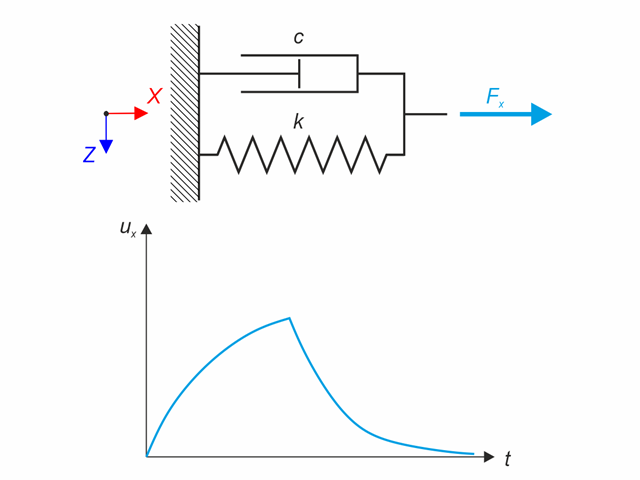
Kelvin-Voigt material model consists of the linear spring and viscous damper connected in parallel. In this verification example there is tested the time behaviour of this model during the loading and relaxation in a time interval 24 hours. The constant force Fx is applied for 12 hours and the rest 12 hours is the material model free of load (relaxation). The deformation after 12 and 20 hours is evaluated. Time History Analysis with Linear Implicit Newmark method is used.
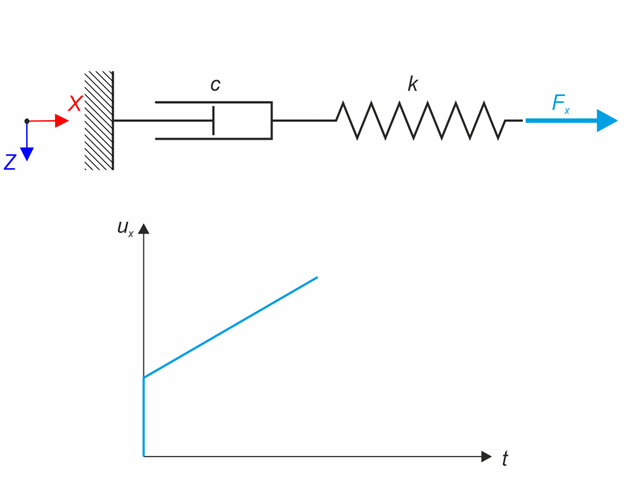
Maxwell material model consists of the linear spring and viscous damper connected in series. In this verification example there is tested the time behaviour of this model. The Maxwell material model is loaded by constant force Fx. This force causes initial deformation thanks to the spring, the deformation is then growing in time due to the damper. The deformation is observed at time of loading (20 s) and at the end of the analysis (120 s). Time History Analysis with Linear Implicit Newmark method is used.
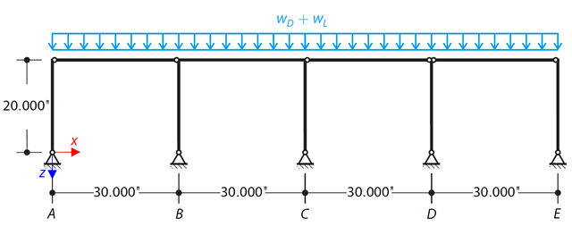
Determine the required strengths and effective length factors for the ASTM A992 material columns in the moment frame shown in Figure 1 for the maximum gravity load combination, using LRFD and ASD.
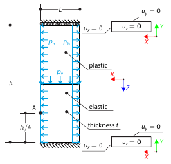
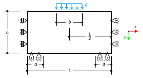
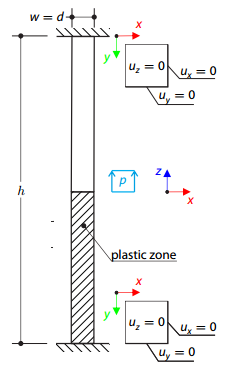
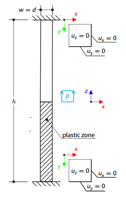
Determine the maximum deformation of a wall divided into two equal parts. The upper and lower parts are made of an elasto-plastic and an elastic material, respectively, and both end planes are restricted to move in the vertical direction. The wall's self-weight is neglected; its edges are loaded with horizontal pressure ph, and the middle plane by vertical pressure.
A cantilever is fully fixed on the left end and loaded by a bending moment on the right end. The material has different plastic strengths under tension and compression.
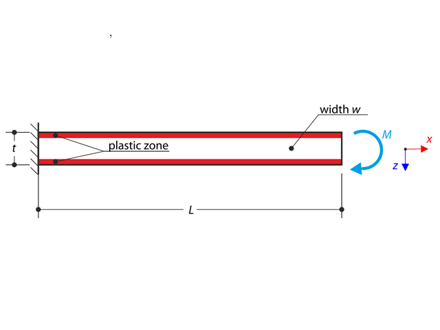
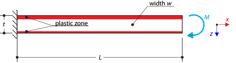
A cantilever is fully fixed on the left end and loaded by a bending moment. Plastic material is considered for the calculation.
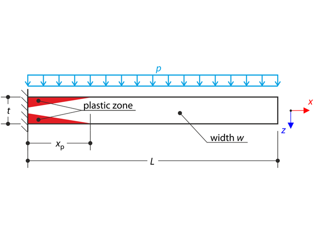
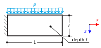
A thin plate is fully fixed on the left end and loaded by uniform pressure. Plastic material is considered for the calculation.
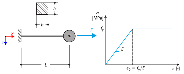
This verification example is based on Verification Example 0122. A single-mass system without damping is subjected to an axial loading force. An ideal elastic-plastic material with characteristics is assumed. Determine the time course of the end-point deflection, velocity, and acceleration.
Determine the required strengths and effective length factors for the ASTM A992 material columns in the moment frame shown in Figure 1 for the maximum gravity load combination, using LRFD and ASD.

A column is composed of a concrete section (rectangle 100/200) and a steel section (profile I 200). It is subjected to pressure force. Determine the critical load and corresponding load factor. The theoretical solution is based on the buckling of a simple beam. In this case, two regions have to be taken into account due to different moments of inertia and material properties.
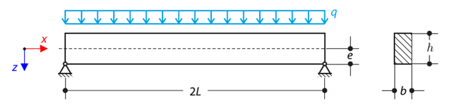
A pinned beam with a rectangular cross‑section is subjected to distributed loading and shifted vertically by eccentricity. Considering the small deformation theory, neglecting the self‑weight, and assuming that the beam is made of isotropic elastic material, determine the maximum deflection.
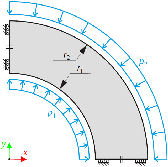
This example is a modification of Verification Example 0061; the only difference is that the material of the vessel is incompressible. An open‑ended, thick‑walled vessel is loaded by both inner and outer pressure. While neglecting self‑weight, the radial deflection of the inner and the outer radius is determined.
A masonry wall is exposed to a distributed load in the middle of its upper section. The Isotropic Masonry 2D material model is compared with the Isotropic Linear Elastic model, with surface stiffness property Without Tension in the nonlinear calculation.
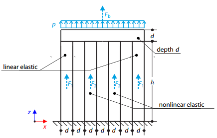
Four columns are fixed at the bottom and connected by a rigid block at the top. The block is loaded by pressure and modeled by an elastic material with a high modulus of elasticity. The outer columns are modeled by linear elastic material and the inner columns by a stress-strain diagram with decaying dependence. Assuming only the small deformation theory and neglecting the structure's self-weight, determine its maximum deflection.
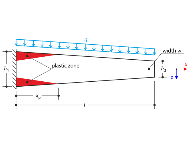
A tapered cantilever is fully fixed on the left end and loaded by a continuous load. Plastic material is considered for the calculation.
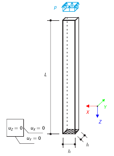
A vertical cantilever with a square cross-section is loaded at the top by tensile pressure. The cantilever consists of an isotropic material. Calculate the deflection.
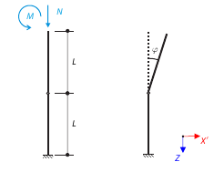
Consider a scaffolding tube connection subjected to an axial force and a moment. Self-weight is not considered. The material of the tube is idealized as perfectly rigid. All geometrical non-linearities are ignored. Determine the angle of deflection.
One layered square orthotropic plate is fully fixed at its middle point and subjected to pressure. Compare the deflections of the plate corners to check the correctness of the transformation.
A three-dimensional block made of elastic-plastic material is fixed at both ends. The block's middle plane is subjected to a pressure load. The surface plasticity is described according to the Tsai-Wu plasticity theory.
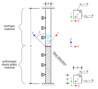
Determine the maximum deflection of a three-dimensional block fixed at both ends. The block is divided in the middle: the upper half is made of an elastic material and the lower part is made of timber - an elasto-plastic othotropic material with the yield surface described according to the Tsai-Wu plasticity theory. The block's middle plane is subjected to vertical pressure.
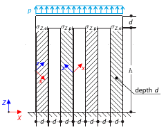
Determine the maximum deflection of four columns fixed at the bottom and connected by a rigid block at the top. The block is loaded by pressure and modeled by an elastic material with a high modulus of elasticity. The outer columns are modeled as orthotropic elastic material, and the inner columns as orthotropic elastic-plastic material with the same elastic parameters as the outer columns and plasticity properties defined according to the Tsai-Wu plasticity theory.
A three-dimensional block made of elastic-plastic material with hardening is fixed on both ends. The block's middle plane is subjected to a pressure load. The surface plasticity is described according to the Tsai‑Wu plasticity theory.
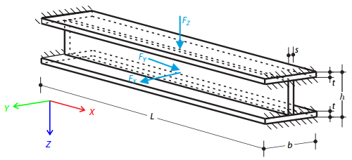
Determine the maximum deflections of the block while considering or neglecting shear effect. The square block of the isotropic material is fully fixed at one end and loaded with uniform vertical pressure.